

Next: GEOM100 Creation of
Up: GEANT
Previous: Logic and algorithm
| Routine ID: GEOM050
| | Author(s): | Submitted: 15.08.83
|
| Origin: R.Brun, A.McPherson | Revised: 08.11.93
|
The GEANT geometry package offers sixteen basic shapes with which
to describe the setups where particles are transported. In this section
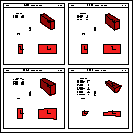
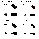
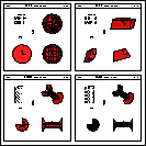
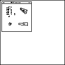
we will describe these shapes. For each shape figs ( ),
(
),
( ), (
), ( ), (
), ( )
show a simple drawing illustrating the
meaning of the parameters and the position and orientation of the
reference frame proper of that shape. A description of the shapes and of
their parameters follows. Angles are always in degrees. With every shape is
given the code which is used internally by GEANT to identify it.
- 1 BOX
- box with faces perpendicular to the
axes. It has 3 parameters:
- DX half-length of the box along the x-axis;
- DY half-length of the box along the y-axis;
- DZ half-length of the box along the z-axis;
- 2 TRD1
- trapezoid with the x dimension varying along z. It has
4 parameters:
- DX1 half-length along x at the z surface positioned
at -DZ;
- DX2 half-length along x at the z surface positioned
at +DZ;
- DY half-length along the y-axis;
- DZ half-length along the z-axis;
- 3 TRD2
- trapezoid with both x and y dimensions varying along z.
It has 5 parameters:
- DX1 half-length along x at the z surface positioned
at -DZ;
- DX2 half-length along x at the z surface positioned
at +DZ;
- DY1 half-length along y at the z surface positioned
at -DZ;
- DY2 half-length along y at the z surface positioned
at +DZ;
- DZ half-length along the z-axis;
- 4 TRAP
- general trapezoid: the
faces perpendicular to z are trapezia and their centres are not necessarily
on a line parallel to the z axis. This shape has 11 parameters, but only
considering that the faces should be planar, only 9 are really independent.
A check is performed on the user parameters and a message is printed in
case of non-planar faces. Ignoring this warning may cause unpredictable
effect at tracking time.
- DZ half-length along the z axis;
- THET polar angle of the line joining the centre of the
face at -DZ to the centre of the one at +DZ;
- PHI azimuthal angle of the line joining the centre of the
face at -DZ to the centre of the one at +DZ;
- H1 half-length along y of the face at -DZ;
- BL1 half-length along x of the side at -H1
in y of the face at -DZ in z;
- TL1 half-length along x of the side at +H1
in y of the face at -DZ in z;
- ALP1 angle with respect to the y axis from the centre
of the side at -H1 in y to the centre
of the side at +H1 in y of the face at -DZ in z;
- H2 half-length along y of the face at +DZ;
- BL2 half-length along x of the side at -H2
in y of the face at +DZ in z;
- TL2 half-length along x of the side at +H2
in y of the face at +DZ in z;
- ALP2 angle with respect to the y axis from the centre
of the side at -H2 in y to the centre
of the side at +H2 in y of the face at +DZ in z;
- 5 TUBE
- tube. It has 3 parameters:
- RMIN inside radius;
- RMAX outside radius;
- DZ half length in z;
- 6 TUBS
-
segment of a tube. It has 5 parameters:
- RMIN inside radius;
- RMAX outside radius;
- DZ half length in z;
- PHI1 starting angle of the segment;
- PHI2 ending angle of the segment;
PHI1 should be smaller than PHI2. If this is not the case,
the system adds 360 degrees to PHI2.
- 7 CONE
- conical tube. It has 5 parameters:
- DZ half-length in z;
- RMN1 inside radius at -DZ in z;
- RMX1 outside radius at -DZ in z;
- RMN2 inside radius at +DZ in z;
- RMX2 outside radius at +DZ in z;
- 8 CONS
-
segment of a conical tube. It has 7 parameters:
- DZ half-length in z;
- RMN1 inside radius at -DZ in z;
- RMX1 outside radius at -DZ in z;
- RMN2 inside radius at +DZ in z;
- RMX2 outside radius at +DZ in z;
- PHI1 starting angle of the segment;
- PHI2 ending angle of the segment;
PHI1 should be smaller than PHI2. If this is not the case,
the system adds 360 degrees to PHI2.
- 9 SPHE
- segment of spherical shell. It has 6 parameters:
- RMIN inside radius of the shell;
- RMAX outside radius of the shell;
- THE1 starting polar angle of the shell;
- THE2 ending polar angle of the shell;
- PHI1 starting azimuthal angle of the shell;
- PHI2 ending azimuthal angle of the shell;
- 10 PARA
- parallelepiped. It has 6 parameters:
- DX half-length in x;
- DY half-length in y;
- DZ half-length in z;
- ALPH angle formed by the y axis and by the plane joining the
centre of the faces parallel to the z-x plane at -DY and +DY;
- THET polar angle of the line joining the centres of the faces
at -DZ and +DZ in z;
- PHI azimuthal angle of the line joining the centres of the faces
at -DZ and +DZ in z;
- 11 PGON
- polygon. It has at least 10 parameters:
- PHI1 the azimuthal angle
at which the volume begins
(angles are counted counterclockwise);
- DPHI opening angle of the volume, which extends from
PHI1 to PHI1+DPHI;
- NPDV number of sides of the cross section between the
given
limits;
- NZ number of planes perpendicular to the z axis where the
dimension of the section is given -- this number should be at least
2 and NP triplets of numbers must follow;
- Z z coordinate of the section;
- RMIN radius of the circle tangent to the sides of the inner
polygon in the cross-section;
- RMAX radius of the circle tangent to the sides of the outer
polygon in the cross-section;
- 12 PCON
- polycone. It has at least 9 parameters:
- PHI1 the azimuthal angle
at which the volume begins
(angles are counted counterclockwise);
- DPHI opening angle of the volume, which extends from
PHI1 to PHI1+DPHI;
- NZ number of planes perpendicular to the z axis where the
dimension of the section is given -- this number should be at least
2 and NP triplets of numbers must follow;
- Z z coordinate of the section;
- RMIN radius of the inner circle in the cross-section;
- RMAX radius of the outer circle in the cross-section;
- 13 ELTU
- elliptical cross-section tube. It has three parameters:
- P1 semi-axis of the ellipse along x;
- P2 semi-axis of the ellipse along y;
- DZ half-length in z;
The equation of the surface is
.
- 14 HYPE
- hyperbolic tube, i.e. the inner and outer surfaces are
hyperboloids, as would be formed by a system of cylindrical
wires which were then rotated tangentially about their
centres. It has 4 parameters:
- RMIN inner radius at z=0, where tube is narrowest;
- RMAX outer radius at z=0, where tube is narrowest;
- DZ half-length in z;
- THET stereo angle of rotation of the two faces;
The hyperbolic surfaces are given by:
- 28 GTRA
- general twisted trapezoid: the
faces perpendicular to z are trapezia and their centres are not necessarily
on a line parallel to the z axis as the TRAP; additionally, the
faces may be twisted so that none of their edges are parallel.
It is a TRAP shape, except that it is twisted
in the x-y plane as a function of z.
The parallel sides perpendicular to the z axis
are rotated with respect to the x axis by an angle
TWIST, which is one of the parameters. The shape is defined by the eight
corners and is assumed to be constructed of straight lines joining points on
the boundary of the trapezoidal face at z=-DZ to the corresponding points on the
face at z=DZ. Divisions are not allowed. It has 12 parameters:
- DZ half-length along the z axis;
- THET polar angle of the line joining the centre of the
face at -DZ to the centre of the one at +DZ;
- PHI azimuthal angle of the line joining the centre of the
face at -DZ to the centre of the one at +DZ;
- TWIST twist angle of the faces parallel to the x-y plane
at z =
DZ around an axis parallel to z passing through their
centre;
- H1 half-length along y of the face at -DZ;
- BL1 half-length along x of the side at -H1
in y of the face at -DZ in z;
- TL1 half-length along x of the side at +H1
in y of the face at -DZ in z;
- ALP1 angle with respect to the y axis from the centre
of the side at -H1 in y to the centre
of the side at +H1 in y of the face at -DZ in z;
- H2 half-length along y of the face at +DZ;
- BL2 half-length along x of the side at -H2
in y of the face at +DZ in z;
- TL2 half-length along x of the side at +H2
in y of the face at +DZ in z;
- ALP2 angle with respect to the y axis from the centre
of the side at -H2 in y to the centre
of the side at +H2 in y of the face at +DZ in z;
Note: this shape suffers from the same limitations than the TRAP:
the tracking routines assume that the faces are planar, but this constraint
is not easily expressed in terms of the 12 parameters. Additionally, no check
on the faces is performed in this case. Users should avoid to use this shape
as much as possible, and if they have to do so, they should make sure that the
faces are really planes. If this is not the case, the result of the transport
is unpredictable.
To accelerate the computations necessary for transport, 18 additional
parameters are calculated for this shape:
- DX0DZ
of the line joining the centres of the faces at
z=
DZ;
- DY0DZ
of the line joining the centres of the faces at
z=
DZ;
- X01 x at z=0 for line joining the
+ on parallel side, perpendicular corners at z=
DZ;
- Y01 y at z=0 for line joining the
+ on parallel side, + on perpendicular corners at z=
DZ;
- DXDZ1
for line joining the + on parallel side,
+ on perpendicular corners at z=
DZ;
- DYDZ1
for line joining the + on parallel side,
+ on perpendicular corners at z=
DZ;
- X02 x at z=0 for line joining the - on parallel side,
+ on perpendicular corners at z=
DZ;
- Y02 y at z=0 for line joining the - on parallel side,
+ on perpendicular corners at z=
DZ;
- DXDZ2
for line joining the - on parallel side,
+ on perpendicular corners at z=
DZ;
- DYDZ2
for line joining the - on parallel side,
+ on perpendicular corners at z=
DZ;
- X03 x at z=0 for line joining the - on parallel side,
- on perpendicular corners at z=
DZ;
- Y03 y at z=0 for line joining the - on parallel side,
- on perpendicular corners at z=
DZ;
- DXDZ3
for line joining the - on parallel side,
- on perpendicular corners at z=
DZ;
- DYDZ3
for line joining the - on parallel side,
- on perpendicular corners at z=
DZ;
- X04 x at z=0 for line joining the + on parallel side,
- on perpendicular corners at z=
DZ;
- Y04 y at z=0 for line joining the + on parallel side,
- on perpendicular corners at z=
DZ;
- DXDZ4
for line joining the + on parallel side,
- on perpendicular corners at z=
DZ;
- DYDZ4
for line joining the + on parallel side,
- on perpendicular corners at z=
DZ;
- 29 CTUB
- cut tube, a tube cut at the extremities with planes
not necessarily perpendicular to the z axis. It has 11 parameters:
- RMIN inside radius;
- RMAX outside radius;
- DZ half length in z;
- PHI1 starting angle of the segment;
- PHI2 ending angle of the segment;
- LX x component of a unit vector perpendicular to the face at -DZ;
- LY y component of a unit vector perpendicular to the face at -DZ;
- LZ z component of a unit vector perpendicular to the face at -DZ;
- HX x component of a unit vector perpendicular to the face at +DZ;
- HY y component of a unit vector perpendicular to the face at +DZ;
- HZ z component of a unit vector perpendicular to the face at +DZ;
PHI1 should be smaller than PHI2. If this is not the case,
the system adds 360 degrees to PHI2.

Figure: shapes BOX, TRD1, TRD2, TRAP

Figure: shapes TUBE, TUBS, CONE, CONS

Figure: shapes PARA, SPHE, PGON, PCON

Figure: shapes GTRA
GEOM100


Next: GEOM100 Creation of
Up: GEANT
Previous: Logic and algorithm
Janne Saarela
Mon Apr 3 12:46:29 METDST 1995
![]() ),
(
),
(![]() ), (
), (![]() ), (
), (![]() )
show a simple drawing illustrating the
meaning of the parameters and the position and orientation of the
reference frame proper of that shape. A description of the shapes and of
their parameters follows. Angles are always in degrees. With every shape is
given the code which is used internally by GEANT to identify it.
)
show a simple drawing illustrating the
meaning of the parameters and the position and orientation of the
reference frame proper of that shape. A description of the shapes and of
their parameters follows. Angles are always in degrees. With every shape is
given the code which is used internally by GEANT to identify it.